
Product compatibility
Fits both DL-6 and VanDOOR AluLIFT.
Reference verified on the VanDOOR ranges below. Any out-of-scope install requires engineering validation.
Compatible range
Technical specifications
1 documented specification
Headline spec
Diámetro
Product compatibility
Reference verified on the VanDOOR ranges below. Any out-of-scope install requires engineering validation.
Compatible range
Related documentation
Manuals and datasheets referenced for this part.
FAQ de pieza
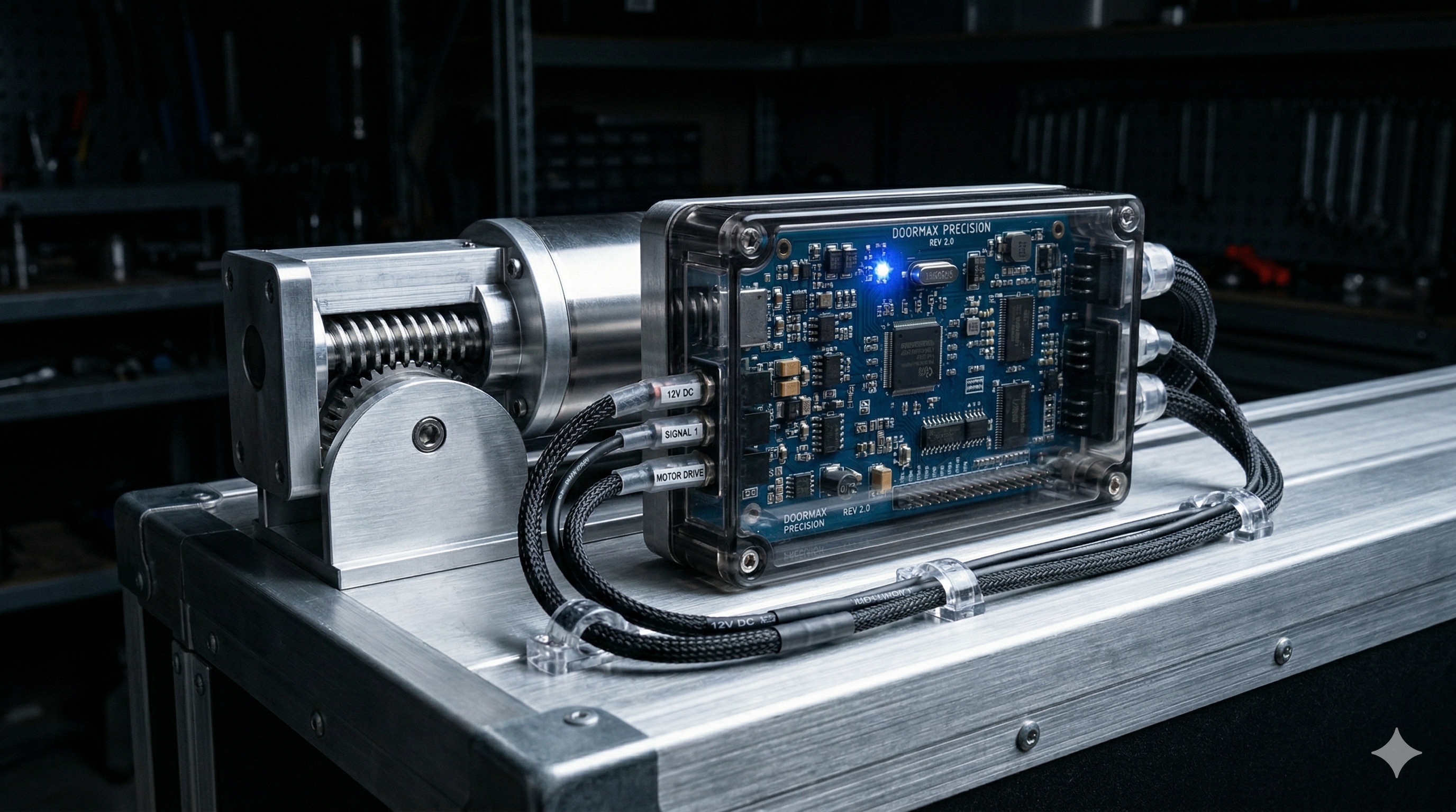
The control box carries two diagnostic LEDs. Key states: LED 1 steady green = power OK, system idle; LED 1 green flashing at 1 Hz = running; LED 1 red flashing = supply too low (check battery and cable); LED 1 off = no power (check 30 A fuse). LED 2 orange flashing = signal received OK; LED 2 orange steady = motor overload or obstruction; LED 2 red steady = cycle-time overrun (weak motor or sensor not reached); LED 2 orange flicker = contact-lock active (AluLIFT). Full chart in the DL-6 user manual and AluLIFT maintenance manual.
SRCFR---Manuel-utilisateur-DL-6.mdl.651-687 + maintenance l.242-273
The system automatically detects under-voltage: LED 1 flashing red in operation means the input is too low. The box cuts the cycle to avoid running motors under-volted. Procedure: (1) check battery voltage (12 or 24 V depending on vehicle) and state of charge; (2) visually inspect battery-to-control-box cables for corrosion or breaks; (3) check the 30 A fuse. Poorly maintained or deeply discharged batteries may fail to run the system. On a trailer, plan an auxiliary supply when the tractor is disconnected.
SRCFR---Manuel-utilisateur-DL-6.mdl.653, 663-664
The motor-unit must be replaced after 5 years or 160,000 cycles, whichever comes first. Verbatim source: VanDOOR AluLIFT maintenance manual v03-2026 §5.1 — “Replace the motor-unit after 5 years or 160.000 cycles”. On the basis of 40 cycles/day × 5 days/week (~10,000 cycles/year), 160,000 cycles equate to about 16 theoretical years — the 5-year threshold therefore becomes the limiting criterion at standard usage. At heavier usage, anticipate the replacement on the cycle counter.
SRCManuel-instruction-maintenance-AluLIFT_v03-2026.pdfl.§5.1 / p.11
Reflejos de campo
Procedimientos críticos para mantenerse operativo — desbloqueo de emergencia y cualificación del instalador.
External release procedure: (1) insert the DoorLIFT key into the lock cylinder at the centre of the intermediate or top panel, outside face; (2) turn the key 90° clockwise and firmly pull the lock and cable out of the cylinder — the system disengages; (3) reinsert the cable and cylinder into the door lock housing, then operate the door by hand. On the AluLIFT, an internal release is available: pull the red sleeve marked 'EMERGENCY DOOR RELEASE' to disengage the motor lever from inside the box.
SRCFR---Manuel-utilisateur-DL-6.mdl.617-632 + utilisation l.420-449
VanDOOR does not perform installation itself. AluLIFT integration must be carried out exclusively by qualified, trained bodybuilders or integrators, in accordance with Machinery Directive 2006/42/EC and best practice. The integrator guarantees regulatory compliance of the final assembly, verifies correct operation, commissions the system, and supplies the end user with the manual and CE Declaration of Conformity for the integrated equipment.
SRCManuel-instruction-installation.mdl.45-72