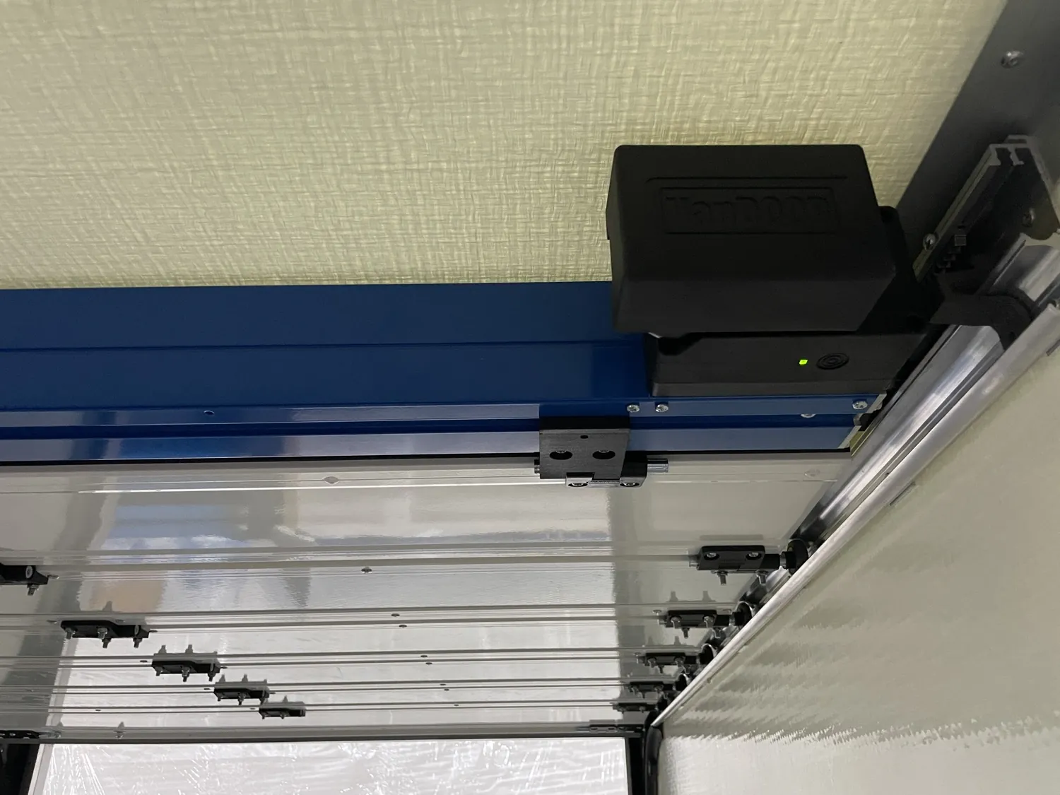
LED diagnostics
LED diagnostic table — colours × sequences
The maintenance manual maps each LED combination on the control box (colour, sequence) to the function or fault it signals, with an explanation.
VanDOOR AluLIFT maintenance manual

For workshops & maintenance
Documented 8-state LED diagnostic, a spare-parts catalogue kept up to date, manuals FR · EN · DE · NL for the DL-6 and FR for the AluLIFT. Built for technicians with little time.
Your challenges
Friction points reported by European workshop managers working on DL-6 and AluLIFT.
Without a clear LED map, a technician loses 15 to 30 minutes isolating the cause of a motor, sensor or electronics fault. The truck holds up the customer's entire logistics chain.
Part reference from a printed PDF catalogue, cross-checked against an engraved serial number: the slightest typo means the wrong part delivered and the truck off the road again at D+3.
Call the sales rep, wait for the email reply: no way to promise the customer the truck back on the road this Friday without certainty that the reference is actually in stock.
Without a 3 / 6 / 12-month maintenance schedule matched to actual use (cycles/day), wear parts (guide pads, balancer, motor unit) fail at the worst moment — often mid-route.
How VanDOOR responds
Sourced from the official DL-6 and AluLIFT maintenance manuals — available now.
The maintenance manual maps each LED combination on the control box (colour, sequence) to the function or fault it signals, with an explanation.
VanDOOR AluLIFT maintenance manual
Each part reference shows compatibility (DL-6 / AluLIFT / both), stock status, indicative lead time and price. No more cross-checking two PDFs.
VanDOOR spare-parts catalogue
Each maintenance window's operations and the references to keep in stock, for a fleet running 40 cycles/day: DL-8001254 guide pads replaced yearly (set of 4), balancer every 1.5–2 years, motor unit at 5 years.
Maintenance plan — Spare parts page
Workshop guide (preventive and curative): 3 / 6 / 12-month intervals, periodic checks, troubleshooting, wear parts and torque values. Available in French for the AluLIFT, in FR · EN · DE · NL for the DL-6.
VanDOOR AluLIFT maintenance instruction manual (Version 03-2026)
Typical workflow
The workshop standard — based on workshop-manager practice reported by our partner network.
Read the LED code against the maintenance manual's table, isolate the cause (power supply, motor, sensor, balancer).
Reference found on /parts, added to the quote cart, stock and lead time confirmed in real time.
Maintenance-manual procedure, torque values respected, full cycle test, anti-crush check.
Vehicle maintenance log updated, next preventive due date sent to the fleet customer.
Resources for you
DL-6 and AluLIFT user and maintenance manuals — free to download.
Workshop FAQs
Five questions sourced from the DL-6 and AluLIFT manuals — emergency release, guide pads, balancer, battery.
The FOB remote runs on an A23 dry-cell — 12 V, replace if range drops or the remote becomes intermittent. Replacement is scheduled at the annual service. Universal reference available in retail. No specific tooling required.
External release procedure: (1) insert the DoorLIFT key into the lock cylinder at the centre of the intermediate or top panel, outside face; (2) turn the key 90° clockwise and firmly pull the lock and cable out of the cylinder — the system disengages; (3) reinsert the cable and cylinder into the door lock housing, then operate the door by hand. On the AluLIFT, an internal release is available: pull the red sleeve marked 'EMERGENCY DOOR RELEASE' to disengage the motor lever from inside the box.
The official schedule mandates an inspection at 3 months (AluLIFT only), at 6 months (DL-6 and AluLIFT), and annually (both). Calculation basis: 40 cycles per day, 5 days per week — about 10,000 cycles/year. For heavier usage, scale inspection frequency accordingly. DoorLIFT service must always be performed alongside the door's own service. Time budget: 30 minutes for the half-yearly service, 60 minutes for the annual service.
Never apply grease or oily product to the DoorLIFT system. Grease coats surfaces and attracts dust, dirt and salt — accelerating wear on pinions and guide blocks. Clean only with a damp cloth. Do not use volatile substances: static electricity can ignite them. However, do lubricate the hinge axles, drum bearings and balancer springs of the door itself (not the DoorLIFT). Also lubricate the emergency-release lock at every 3-month service.
The four guiding blocks (ref. DL-8001254) must be replaced at every annual inspection. They are the highest-frequency consumable in the system — one system = four blocks per year. Replacement is explicitly listed in both ranges' maintenance schedules (DL-6 and AluLIFT). The part is common to both. Keep a few sets in stock at the workshop if you operate more than 5 equipped vehicles.
Next step
Parts catalogue online, part quotes within 24 h, technician training on site or by video call. Our after-sales team answers in French, English and Dutch.
Field essentials
Critical procedures to stay operational — emergency release and installer qualification.
External release procedure: (1) insert the DoorLIFT key into the lock cylinder at the centre of the intermediate or top panel, outside face; (2) turn the key 90° clockwise and firmly pull the lock and cable out of the cylinder — the system disengages; (3) reinsert the cable and cylinder into the door lock housing, then operate the door by hand. On the AluLIFT, an internal release is available: pull the red sleeve marked 'EMERGENCY DOOR RELEASE' to disengage the motor lever from inside the box.
VanDOOR does not perform installation itself. AluLIFT integration must be carried out exclusively by qualified, trained bodybuilders or integrators, in accordance with Machinery Directive 2006/42/EC and best practice. The integrator guarantees regulatory compliance of the final assembly, verifies correct operation, commissions the system, and supplies the end user with the manual and CE Declaration of Conformity for the integrated equipment.